The user is free to place the IDS flow controller near the NAIS is any way, as long as the IDS box remains upright (± 15°) during operation.

The total length of the sampling line from the aerosol source through the mixer to the NAIS should be as small as possible. However, if it is necessary to extend the inlet line then it is preferable to increase the length between the mixer and the NAIS and keep the mixer as close to the aerosol source as possible.
A conductve tube with 32 mm inner diameter should be used to extend the NAIS inlet tube.
Attention: All parts of the sampling line must be electrically conductive and grounded to the zero potential. The mixer head has a M4 threaded hole that can be used to attach a grounding wire to it. Other tubing used for connecting the IDS to the NAIS does not need to be conductive.
The IDS flow controller should be connected to the NAIS outlets and to the mixer using tubing with an inner diameter of at least 10 mm. A larger diameter (e.g. 20 mm) is preferred. The length of tube from the IDS flow controller to the IDS mixer should be kept small because the flow rate is high and a long and narrow tube will strain the NAIS sample flow blowers.
Attention: Before connecting the data cable, first the NAIS and IDS should be connected to the a mains power socket with proper grounding.
The IDS flow controller RS-232 port must be connected to the NAIS USB port using the included RS-232-USB cable. (Note: the NAIS does not need to be switched off when connecting or disconnecting the USB port)
When the IDS is connected and switched on, then the NAIS data acquisition software will automatically detect it after a few seconds. After the IDS is properly detected then the "Diluter flow" value should appear on the NAIS status display.
The measurement software will start showing the value for the "Diluter flow" measurement variable as well. One second average records will be the first to start showing the dilution flow value.

The diluter flow parameter can be configured in the measurement software using the "Adjust parameters" command.

Select the diluter flow parameter in the "Parameter adjust" window and use the "Set value" button to set the value you wish. The new diluter flow value will be applied immediately. However it will take a few seconds for the flow to stabilise.
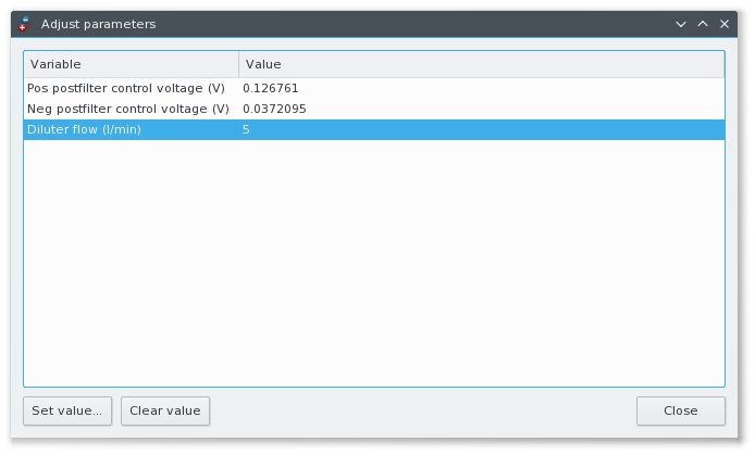
Check the flow values in the measurement variables window. The "Diluter flow target" parameter shows the effective target diluter flow value. The actual measured flow rate is shown by the "Diluter flow" parameter.
Confirm that the actual diluter sample flow matches the target value. If the actual flow is smaller than the requested value then it may be necessary to switch on the internal blower of the IDS flow controller. The IDS blower may be kept on always during the experiment to make sure that the flow rate is correct.
Also confirm that both the positive and negative sample flows are correct (27 l/min) and the sample flow blowers are not overstrained. The measurement software would show a warning that the blower control voltage is near maximum. If that is the case then it may indicate that the tube connecting the IDS flow controller and the mixer, or the tubes connecting the NAIS and the IDS flow controller are too long or too narrow.
At this moment the measurement software does not automatically correct the particle concentrations based on the diluter flow. However the diluter sample flow rate is stored with the measurement results (in the .record files) and the correction can be easily applied manually during data processing.
The measured concentrations should be multiplied with the coefficient 54/x where x is the actual diluter flow in l/min.
